Buyer's guide of Powell Lenses
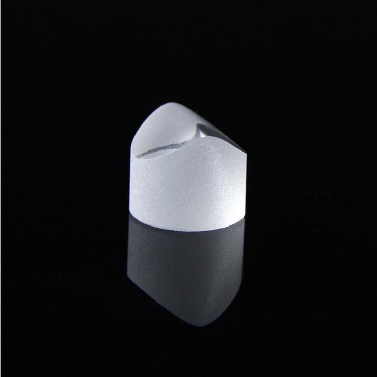
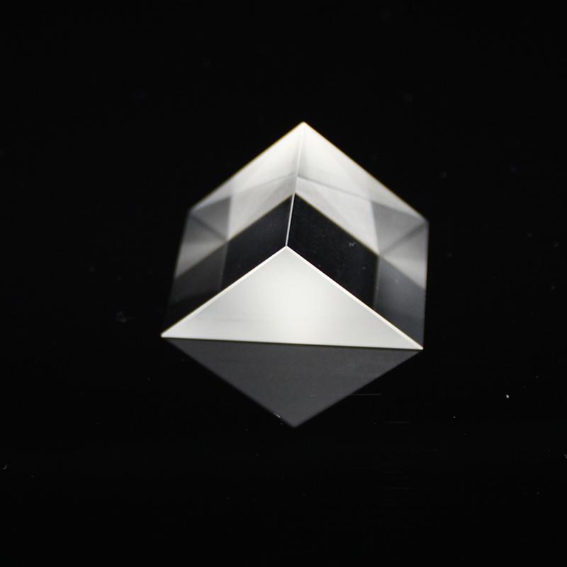
The Powell lens resembles a round prism with a curved roof line. The lens is a laser line generator, stretching a narrow laser beam into a uniformly illuminated straight line.
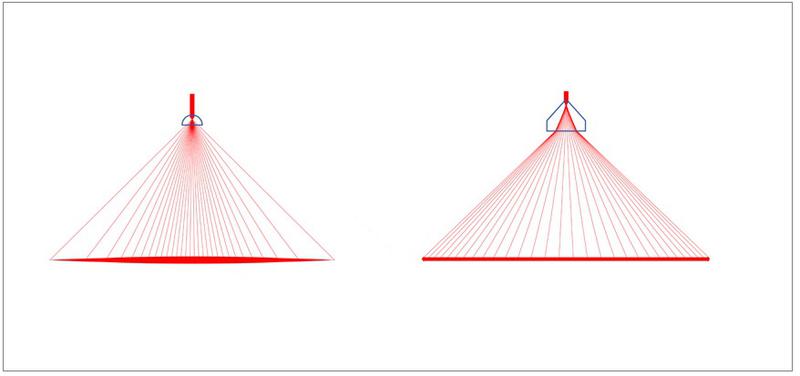
The Powell lens is a quantum leap forward in line generator performance over the simple cylinder lens. A cylinder lens produces a poorly illuminated line, one limited by the non-uniform, Gaussian laser beam. The Powell lens' rounded roof is in fact a complex two-dimensional aspheric curve that generates a tremendous amount of spherical aberration that redistributes the light along the line; decreasing the light in the central area while increasing the light level at the line's ends. The result is a very uniformly illuminated line used in all manner of machine vision applications; from bio-medical to automobile assembly.
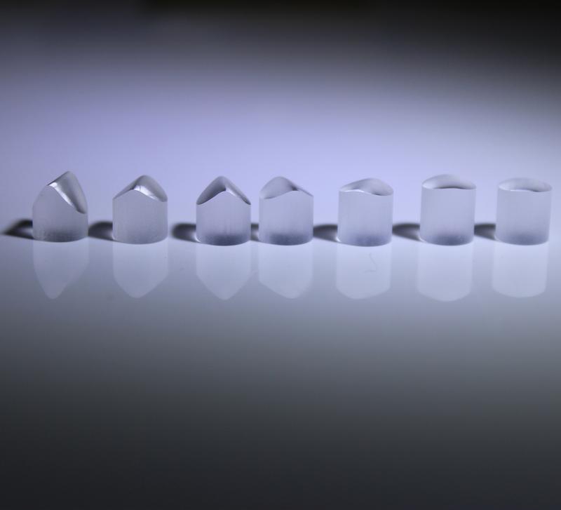
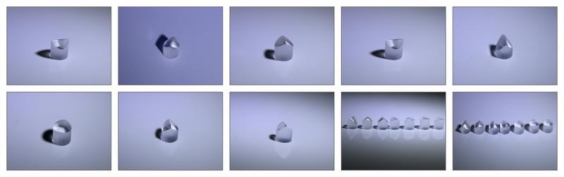
Fan Angle
The width of the Powell lens fan angle is a function of the refractive index of the glass and the roof angle. The steeper the roof and the higher the refractive index, the wider the fan angle and the longer the line for a given projection distance. Small fan angles typically use optical glass of a moderate, n=1.5, refractive index. Large fan angles are best made with a high index glass, n= 1.8, or higher to minimize the roof's otherwise steep angle.
VY Optoelectronics Co.,Ltd. stocks 9mm diameter lenses with 1°, 5°, 10°, 15°, 20°, 30°, 45°, 60°, 75°,90° and 110°. VY Optics can also manufacture custom fan angles with low costs.

Laser Beam Size
The incident laser beams dimension determines the laser line thickness at a given projection distance. A collimated laser diode features an elliptical beam cross section allowing either a thin or thick line capability with a single diode module.
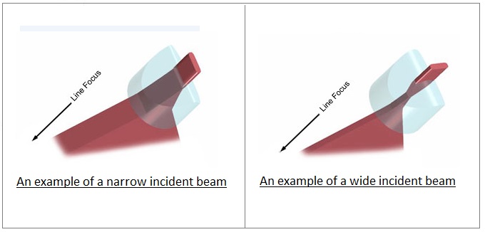
With a narrow incident beam orientation, the beam's major axis is parallel to the Powell lens roof and a thin laser line with a small depth of focus is generated. With a wide incident beam orientation, the beam's major axis is perpendicular to the Powell lens roof and a thick laser line with a large depth of focus is generated. In the above graphics the diverging fan is truncated close to the lens. For each case, the beam is focused onto a CCD array at the 500mm working distance. The images below clearly show the effect of beam shape/orientation on the line width.

The Powell lens performance and physical characteristics are driven by the beam width. The most significant differences being the diverging fan's foot print on the flat exit face that serves as the mounting surface. Care must be taken to ensure that mounting hardware does not clip the diverging light.
Line Uniformity
Powell lens performance is sensitive to the incident laser beam's characteristics as well as the quality of the lens' aspheric surface. For demanding applications, a uniformly illuminated laser line is best achieved by matching the Powell lens to the laser module's particular beam characteristics.

Powell lens uniformity is not an absolute characteristic, it is dependent on the testing technique. For example, the uniformity measure will depend on whether one is assessing the Powell lens's projected line as seen on a surface by a camera in a machine vision application or sweeping a detector across the diverging fan of light for laser safety assessment. The differences in uniformity characteristics increase with fan angle, beyond 20 degree Powell lens divergence the differences become significant.
Contained Power
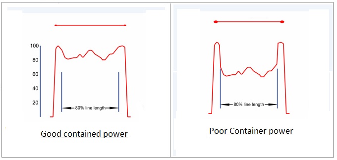
The central 80% of a uniformly illuminated line will contain 80% of the energy. A lower contained energy will cause the ends of the lines to increase in brightness. Minimizing the peaks helps to better utilize the laser's available power. Illustrated are two lines with identical uniformity that differ significantly in contained power.
Laser Line Straightness and Boresight
Line straightness and boresight deviation is dependent on Powell lens quality of manufacture as well as the precision of its mounting in the laser module. The Powell lens cell and its interface with the laser must be carefully designed and manufactured to maintain the roof's perpendicularity to the incident light, otherwise line curvature will be induced. Wedge between the Powell lens' roof and exit face will result in a boresight error, a displacement of the line from the target position established by the laser alone. Assuming the lens mounting is perfect, the lens wedge will tilt the roof slightly and induce line curvature.
Mounting the Powell Lens
Careful consideration is required for mounting the Powell lens to ensure there is no clipping of the diverging beam emanating from the lens' plano exit face. Because of the complex ray paths of the Powell lens, clipping a large fan angle light beam close to the exit surface will alter line uniformity. The incident laser beam diameter defines the Powell lens roof shape and thus beam foot print size on the plano exit face. Because of ray clearance issues, the standard 90° Powell lens is only offered in the wider incident laser beam orientation with a large depth of focus.